Introduction
Optics production drawings play a pivotal role in the manufacturing process of optical components, devices, and systems. These drawings serve as detailed blueprints that guide engineers, technicians, and manufacturers in fabricating precise and high-quality optical products. Here’s an overview of their importance:
1. Accuracy and Precision: Optics production drawings provide precise specifications, including dimensions, tolerances, surface finishes, and material requirements. This level of detail ensures that optical components are manufactured to exact specifications, crucial for maintaining performance and functionality.
2. Quality Control: By outlining specific tolerances and quality standards, production drawings facilitate effective quality control measures throughout the manufacturing process. Manufacturers can inspect and verify each component against the drawing to ensure it meets the required specifications.
3. Consistency: Optics production drawings help maintain consistency in manufacturing, ensuring that every optical component produced conforms to the same standards. This consistency is vital for applications where uniformity and repeatability are critical, such as in optical systems used in scientific research or industrial processes.
4. Communication and Collaboration: Production drawings serve as a common language between designers, engineers, and manufacturers. They communicate design intent and requirements clearly, minimizing misunderstandings and errors that can arise during the manufacturing process. Effective communication streamlines collaboration and ensures that everyone involved in production is aligned with the design objectives.
5. Cost Efficiency: By providing detailed specifications upfront, optics production drawings help reduce the likelihood of errors or rework during manufacturing. This can lead to cost savings by minimizing material waste, reducing production time, and avoiding costly mistakes that could result in product defects or failures.
6. Customization and Innovation: Optics production drawings are essential for customizing optical components to meet specific requirements. Whether it’s adjusting the shape, size, or optical properties, detailed drawings guide manufacturers in producing tailored solutions for various applications. Additionally, these drawings support innovation by providing a framework for experimenting with new designs and technologies.
7. Documentation and Traceability: Production drawings serve as essential documentation throughout the product lifecycle. They provide a record of the design specifications and manufacturing processes, enabling traceability and accountability. This documentation is valuable for troubleshooting, maintenance, and future product iterations.
Basics of Optics Production Drawings
Optics production drawings are technical documents that provide detailed instructions for manufacturing optical components and systems. Understanding the basics of these drawings involves familiarity with key terminologies and principles used in optical design and manufacturing. Here’s an overview:
1. Optical Components: These are the individual parts that make up optical systems, such as lenses, mirrors, prisms, filters, and optical fibers.
2. Design Specifications: Optics production drawings specify various parameters essential for the design and fabrication of optical components. This includes dimensions, shapes, surface quality, material properties, optical properties (such as refractive index and dispersion), and coating requirements.
3. Tolerances: Tolerances define the allowable deviation from specified dimensions or properties. In optics, tight tolerances are often necessary to ensure the desired optical performance. Tolerance values are typically specified in units like micrometers (µm) or nanometers (nm).
4. Surface Finish: The surface finish of optical components is critical for their performance. Parameters like roughness, flatness, and parallelism are specified to ensure the required surface quality, which affects light transmission, reflection, and scattering.
5. Coatings: Optical coatings are thin layers applied to optical surfaces to modify their reflective, transmissive, or absorptive properties. Production drawings specify coating materials, thicknesses, and spectral characteristics to achieve desired optical effects, such as anti-reflection coatings or wavelength filters.
6. Geometric Optics: Geometric optics deals with the behavior of light rays as they propagate through optical systems. Basic concepts include ray tracing, focal length, aperture size, and image formation, all of which influence the design and performance of optical components.
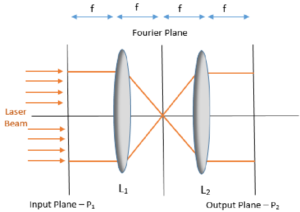
7. Wave Optics: Wave optics considers the wave nature of light and phenomena such as interference, diffraction, and polarization. Understanding these principles is crucial for designing advanced optical components like diffractive optical elements or polarizing optics.
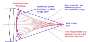
8. Lens Design Parameters: For optical lenses, key design parameters include focal length, aperture diameter, curvature, and aberrations (such as spherical aberration, chromatic aberration, and coma). These parameters are specified in production drawings to ensure the lens meets performance requirements.
9. CAD Software: Computer-Aided Design (CAD) software is commonly used to create optics production drawings. CAD tools enable designers to accurately model optical components, specify dimensions and tolerances, and generate detailed manufacturing drawings.
10. ISO Standards: International Organization for Standardization (ISO) standards provide guidelines for optics manufacturing and quality assurance. Production drawings often adhere to ISO standards to ensure compatibility, consistency, and quality across different manufacturers and industries.
Deciphering ISO 10110 Standards
The most commonly used standard for optics manufacturing is ISO 10110, first created in 1927.ISO 10110 is a series of international standards developed by the International Organization for Standardization (ISO) specifically for specifying optical elements and systems.
These standards provide a systematic framework for defining the requirements and parameters of optical components in a standardized manner. ISO 10110 plays a crucial role in ensuring consistency, quality, and interoperability across the optics industry. Let’s delve into a detailed explanation of ISO 10110 and its significance in optics:
Structure of ISO 10110:
- ISO 10110 is organized into several parts, each addressing different aspects of optical elements and systems. The standard covers various types of optical components, including lenses, mirrors, prisms, filters, and windows.
- Each part of ISO 10110 focuses on specific topics such as dimensional tolerances, surface quality, coatings, and material specifications relevant to optical elements.
- The standard provides a structured format for documenting optical specifications, facilitating clear communication between designers, manufacturers, and end-users.
Specification Parameters:
- ISO 10110 specifies a comprehensive set of parameters for describing optical components. These parameters include dimensions, tolerances, surface quality, material properties, coatings, and other relevant characteristics.
- Dimensional parameters define the physical size and shape of optical elements, such as diameter, thickness, curvature, and conic constants for lenses.
- Tolerance specifications establish allowable deviations from nominal dimensions, ensuring that manufactured components meet specified requirements.
- Surface quality parameters describe the optical and mechanical properties of surfaces, including roughness, scratches, digs, and irregularities.
- Coating specifications outline requirements for optical coatings, including material composition, thickness, reflectance/transmittance properties, and spectral characteristics.
Standardized Notation:
- ISO 10110 employs a standardized notation system for documenting optical specifications. This notation consists of a series of symbols and numerical codes arranged in a structured format.
- The notation system provides a concise and uniform way to express optical requirements, enhancing clarity and consistency in communication.
- By using standardized notation, ISO 10110 facilitates interoperability between different stakeholders involved in the design, manufacturing, and testing of optical components.
Quality Assurance and Compliance:
- Compliance with ISO 10110 ensures that optical components meet internationally recognized standards for quality and performance.
- The standard provides guidelines for quality assurance practices, including inspection methods, testing procedures, and documentation requirements.
- Manufacturers can use ISO 10110 as a benchmark for ensuring the reliability, repeatability, and traceability of optical manufacturing processes.
Global Adoption and Impact:
- ISO 10110 is widely adopted across the optics industry, serving as a common reference for specifying optical components and systems.
- Its global reach ensures consistency and compatibility in the design and manufacturing of optical products, regardless of geographical location or industry sector.
- By promoting standardization and best practices, ISO 10110 contributes to innovation, efficiency, and competitiveness within the optics industry.
The image below is of a typical lens drawing.
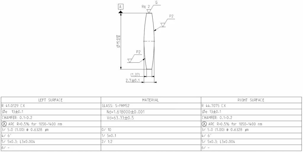
The drawing can be divided into two areas – Drawing Area and Table of Parameters.
Optics production drawing area
Let’s review the drawing area of the biconvex lens seen above.
Need help? Click here to learn more about our custom optical engineering services.
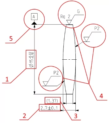
You can see a set of numbered parameters and conventional signs described below.
- Lens diameter – full lens diameter.
- Lens thickness – thickness of a lens along the axis of the base surface.
- Lens edge thickness. This parameter is given for reference. Its value depends on the set of defined (with tolerances) parameters.
- Surface texture – composite conventional sign with set of parameters which defines quality of surface processing.
- Datum surface – surface which define datum axis of the lens. It is possible to see more than one datum surface on different drawings.
Optical coating definitions and standards
According to ISO 10110 standard, optical coatings are divided into protective and functional coatings.
Protective types are coated onto optical elements when the safety of optical surfaces matters and a functional coating is needed. For example, an optical device to be used in a harsh environment requires a protective coating.
Functional types are coated onto optical elements to provide the necessary refractive or reflective coefficient.
Let’s look at a drawing example of an optical lens production shown here. Locate the cell defining optical coating parameters in the surface requirements column.
Table of parameters area
Table of lens parameters is divided into columns.

We can see two columns with requirements for the surface and one column with requirements for the optical element material in the drawing example.
First of all, you will see a Greek letter with a circle around it. This mark indicates that a functional coating is needed. Then the ARC abbreviation follows, short for “Anti Reflection Coating”. This acronym defines the purpose of the coating. In this case, the coating decreases the reflection coefficient.
The next inscription (R<0,5%) is the requirement for maximal reflection coefficient. Last is the wavelength range and optical coating requirements are defined for these wavelengths. In some cases, instead of a range, wavelengths are either more precisely defined or defined as sets of wavelengths. In those cases, the values are separated by commas.
An optical engineer defines optical coating requirements not only from the optical system efficiency’s point of view. They also assess the influence of light reflected from the lens surface onto an image or sensor. Reflected or scattered light can destroy the image quality or worsen the signal to noise ratio making a precise coating definition an important design task.
Column with surface parameters
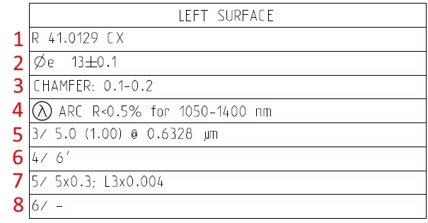
- Radius of curvature value. Convex (CX) or concave (CC).
- Effective (clear) diameter – diameter is meant for light propagation. Remember that optical coating is overlaid only in border of effective diameter.
- Protective bevel.
- Optical coating of the surface – should be meant working wavelength or set of wavelength or spectral range and coefficient of transmitting efficiency in percentage.
- Tolerances on surface form (figure error). First number is the power difference in fringes. Second number (in brackets) is irregularity in fringes. Also wavelength for measurements should be defined.
- Centering – tilt angle of a surface defined as angle between the datum axis and the surface normal. Units – angle minutes and angle seconds.
- Scratch and dig specifications – there is defined all possible surface imperfections.
- Damage threshold of laser irradiation. Generally speaking, this parameter is critical for optical elements which work with high power laser irradiation. This is why this cell is often empty for the remaining optical elements.
Column with material requirements
Column with material requirements is placed between columns with surface parameters.
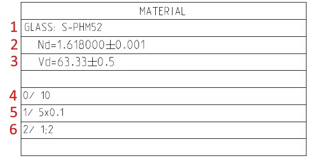
It includes the following items.
- Optical material Name.
- Refractive Index.
- Abbe Number.
- Stress Birefringence – defines maximum allowable stress in nm/cm of optical path length.
- Bubbles and Inclusions – defines number and size of bubbles and inclusions in the optical element.
- Inhomogeneity and Striae – defines homogeneity class number and striae class number.
All requirements and properties of optical elements are defined by optical and mechanical engineers in the course of preparing an optical design.
Even with a published standard, there can be confusion and different interpretations. A best practice is to check with your lens manufacturer about their definitions and questions. For more information, one of the best and most complete online documents to understand this subject is available here
Common Challenges and Solutions
Interpreting optics production drawings can pose several challenges, including complex geometries, tight tolerances, and stringent surface requirements. Common challenges may include dimensional inaccuracies, material selection issues, or coating defects. However, these challenges can be overcome through collaboration, communication, and attention to detail. Solutions may involve using advanced metrology techniques, optimizing manufacturing processes, or refining design specifications to meet performance requirements.
Radius of Curvature Requirement in Optical Drawings
Based on the ISO 10110 standard, one of the key parameters in optical drawings is the radius of curvature of lens surfaces. This parameter is typically listed on the first line of the surfaces column in the table of parameters.
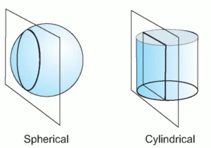
The optical properties of a lens are defined by the shapes of its surfaces. In most cases, lens surfaces are spherical, meaning that each surface is part of a sphere. The radius of curvature is the distance from the center of this sphere to the surface of the lens. Optical engineers specify this radius for each lens surface in the production drawings.
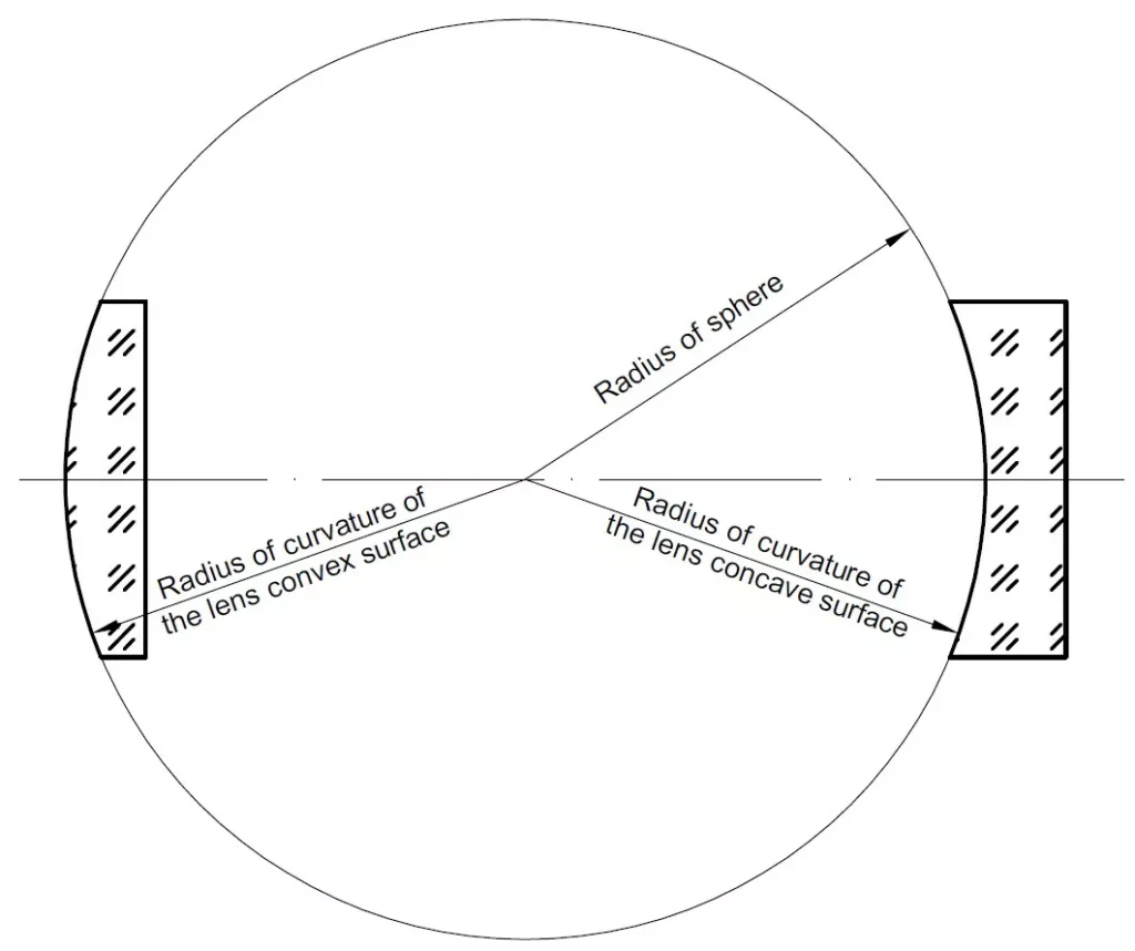
The radius of curvature is critical because it determines the lens’s focal power and effective focal length. Even a small error in calculating this value can significantly impact the performance of an optical system. In optical drawings, you will also find marks indicating whether a lens surface is Convex (CX) or Concave (CC).
Errors in defining the radius of curvature can affect the lens’s ability to focus light correctly, leading to issues like aberrations or reduced optical efficiency.
Conclusion
Understanding optics production drawings and interpreting ISO 10110 standards are essential for ensuring the accuracy, precision, and quality of optical components and systems. By adhering to these standards, manufacturers can achieve consistency, reliability, and interoperability in the design and manufacturing of optical products. Moreover, recognizing key parameters like the radius of curvature is crucial for optimizing lens performance and preventing errors in optical systems.
Frequent Asked Questions Optics Production Drawings
What is the significance of ISO 10110 in optics production drawings?
ISO 10110 standardizes the presentation of design and functional requirements for optical elements, ensuring clarity and precision in optical manufacturing.
How do you interpret surface and material requirements in optical drawings?
Surface and material requirements are detailed specifications, including aspects like curvature, diameter, and optical material properties, which must be accurately interpreted for quality lens production.
Can the principles of optics production drawing interpretation be applied universally?
While the principles are generally applicable, specific standards and conventions can vary, necessitating adaptability and continuous learning in the field of optical engineering.
