A previous post discussed underwater optical design. This week, we will review the diametrical opposite application – free-space optical communication (FSO). As with underwater optical design, one of the challenges facing FSO is the optical signal propagation through a highly variable medium. For example, atmospheric turbulence produces temporary pockets of air with slightly different indices of refraction.
These will randomly change the laser phase-front producing intensity fluctuations and different absorption and scattering. Another challenge is optimal alignment between the transceiver elements. This can be achieved using highly directional and narrow beams of light, tracking errors on the receiver, and generating signal feedback to adjust alignment.
What are Free-space Optical Communications?
FSO are communication systems in which the signal is propagating through the air or vacuum. One of the reasons why FSO are so attractive is because they offer great flexibility and relatively low cost to be deployed while providing high transmission data. For example, FSO networks can be configured for point-to-point, point-to-multipoint, multipoint-to-point, or multipoint-to-multipoint.
On the downside, FSO communication is affected by the mentioned atmospheric effects, which limits sensitivity and achievable data rates
Although the field of FSO also includes optical interconnects and satellite communications, here we will focus on systems where a line of sight between two ground-stations exists.
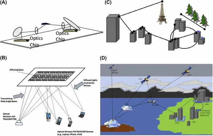
a) Optical Interconnects, b) point-multipoint indoor FSO, c) Terrestrial FSO, d) satellite FSO. After Arun K. Majumdar “Optical Wireless Communications for Broadband Global Internet Connectivity. 2019. Chapter4. Elsevier
Optical Design
To properly design an FSO system, we need to define requirements including range, data rate, and price. In terms of wavelengths, most FSO systems operate in the near-IR wavelength range between 750 and 1600 nm. The reason for this is due to the lower absorption at those wavelengths, although additional development exists at longer wavelengths (>5 micrometers) .
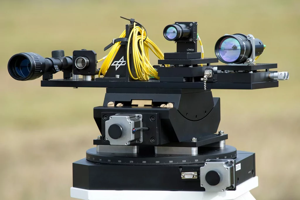
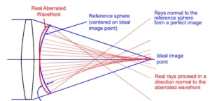
The main purpose of the transmitter optics is to produce a suitable beam divergence matching a desired beam diameter at the receiver. Without transmitter optics, the beam divergence would produce a beam too large to be of practical use (around 200m a distance of 500 m). Moreover, a desired feature of the transmitter optics is that it should add a minimum of aberrations (specially spherical aberration).
The main objective of the receiver is to collect as much as possible of the incoming signal and to couple it either to a photodetector or an optical fiber. Therefore, the design of the receiver tends to be more crucial than the design of the transmitter. An important aspect is its alignment tolerance, i.e. how much the receiver is allowed to deviate from the optical axis.
A common solution for either element of the transceiver is to use a telescope-based configuration (either Galilean or Keplerian), replacing some of the single elements with achromats to reduce spherical aberrations. Most receivers may have multiple input ports. These multiple inputs help reduce the effects of atmospheric aberration and atenuations, as well as a way to make redundant paths and prevent blockage of the optical path.
