In this article, we will continue our description of different optical instruments used by optometrists. Last time we talked about Ophthalmoscopes, today we will talk about another very common optical instrument called the Keratometer.
The keratometer was developed in 1851, it is used to measure the curvature of the anterior cornea. That is the outer layer of the cornea. Keratometers use an object of known size and by modifying the distance to the cornea they create an image of specific size.
The anterior corneal curvature is then obtained from the convex mirror formula and corneal power is calculated using Snell’s law of refraction with simplified optics. To account for errors caused by the cornea thickness and the curvature of the posterior surface keratometers use a refractive index of 1.3375, instead of the more accurate value of 1.376.
When utilizing a keratometer, two images of a target mire are created. Crosses or circles with marks along the outside might be used as the mire. These photos may be out-of-focus, in which case an optical professional will adjust the object’s distance until the image is sharp. The target is denoted by a circle with a cross symbol in the center.
The cross should be in the center of the circle. The curvature is measured using the upper and left markings. We can quantify that curvature by changing those photos until the lateral markers are superimposed. We can observe the three different markings before and after alignment in Figure 1.

It is important to mention that in the case of an astigmatic eye, both marks wont be able to be superimposed simultaneously.
In figure 2 we show a basic layout of a keratometer. We will describe the basic elements, although we won’t be able to mention any of the specific details about the optical components, we will be able to describe their basic functions.
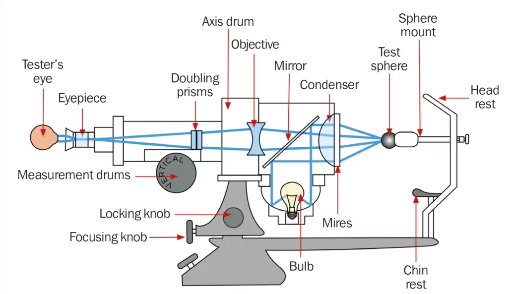
In the figure we are showing a test sphere instead of a patient’s eyes. Several of the components shown are used to control the illumination. The mires are placed on its own mechanical fixture that allows for the control of their position as explained before.
One problems when measuring the cornea curvature, is that the eyes are in constant movement. In order to help stabilize the image long enough to perform the required measurements it is common to use a double prism. Finally we have optical elements that are used to create an image that can be captured by an eyepiece and the operator.
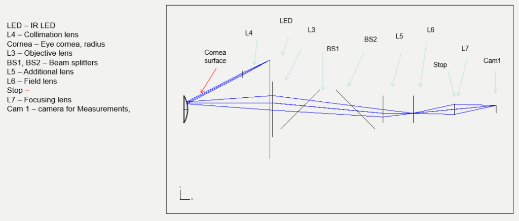
In modern systems it is possible to replace the eye of the operator by a camera. One of such devices is shown in Figure 3. Figure 3 was developed by OpticsForHire, although we can go into details of the system, the basic operation is pretty similar to the one that we just described. Notice that the mires and mechanical positional components are not shown.
