Microscopy is a fundamental technique used to analyze samples that are too small to be perceived without magnification. It is used in multiple sciences, from biology, medicine, chemistry to anthropology, and any science where small samples are presented.
Early microscopes were simple instruments with just a couple of optical elements. As methods improved, so did the resolution and contrast microscopes could provide. One active area of microscopy is Fluorescent microscopy. Fluorescence was discovered in the 1850s by John Frederick William Herschel (son of the famous astronomer William Herschel), and by the early 1900s, the first commercial fluorescent microscope was introduced by Carl Zeiss.
The basic concepts of those early systems are still widely used and in constant evolution. Techniques like confocal microscopy, two-photon microscopy, and many others rely on the basic principles of fluorescent microscopy.
In this article, we talk about the design considerations when developing a scanning fluorescent microscope. We start with some basic definitions, and then go over how to design a system with off-the-shelf components versus custom-made components.
Basic Architectures
Scanning Microscope
In a laser scanning microscope, scanning can be achieved in different ways. One is two move the sample in the x-y directions (and sometimes the z-direction) while keeping the optics fixed. This may limit the resolution of the image to the mechanical performance of the moving stage.
Another technique is to place a mirror that can rotate a couple of degrees on the back focal plane of the scanning lens. This movable mirror can be controlled very precisely by using piezoelectric components. To create a scanning beam, a typical system will have a scanning lens (close to the scanning mirror), a tube lens, and an objective lens.
The scanning mirror is placed at the back focal length of the scanning lens, and the front focal plane of the scanning lens coincides with the back focal plane of the tube lens (forming then an afocal telescope). The tube lens then images the scanning mirror into the objective lens pupil, then to the sample. The design of a scanning microscope with this system requires careful considerations to prevent unwanted aberrations and a proper illumination of the sample.
A compromise between the objective lens NA and transmitted power needs to be achieved. While it is possible to use off-the-shelf components, improvements in performance can be obtained by using custom optics.
An important detail of the design process is the choice of a scanning mirror including its design parameters, whether it is single or dual axis, and the range of motion and frequency. All of these are important parameters that will affect the choice of the rest of the optical components. We have previously built linear and dual-axis scanning mirrors which clients have integrated into scanning microscope systems.
Fluorescent Microscope
A fluorescent microscope is a special kind of microscope that is used to detect the presence of biomolecules in samples. As the name indicates, it is based on fluorescence. Briefly, fluorescence is a kind of light emission in which a sample absorbs light at a specific frequency (and therefore with a very specific amount of energy).
The energy absorbed excites electrons in the sample and when the electrons go back to a more stable state, they emit light at a lower frequency than the one absorbed. It is an instrument that has become indispensable when working with biological samples because it allows the detection of molecules at very small concentrations. Figure 1 shows a small schematic of a simple fluorescent microscope.
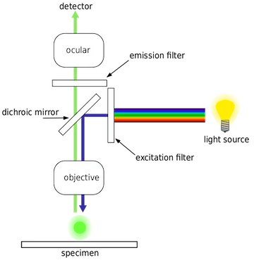
In terms of optical components, a fluorescent microscope requires a very intense light source. Xenon-arc lamps, mercury vapor lamps, lasers, and high-power LEDs are just a few examples of possible sources. After the light source, we have a filter (usually referred to as an excitation filter), where only a very specific wavelength passes through. From this filter, we go to a dichroic mirror.
Dichroic mirrors have a very specific transmission and reflection coefficient for two different wavelengths: they allow one wavelength to be transmitted while reflecting the other wavelength. In our case, we will reflect the light coming from the excitation filter, and this beam will be focused by a lens into a sample.
The sample is then excited by this specific wavelength and fluorescence takes place in the biomolecule we are trying to detect. The light emitted by the biomolecule due to fluorescence is then transmitted back to the dichroic mirror. On this second pass, the emitted light passes through the mirror then through a second filter (this one called emission filter) and then to the ocular or camera.
If the right combination of excitation/emission filters and dichroic mirrors is available, it is possible to excite the sample with different wavelengths and obtain a color image of the biomolecule. Although considerable design effort needs to take place to have the proper illuminations, aberration need to be corrected at each wavelength.
It is also possible to design a scanning fluorescence microscope. A very common example is the two-photon scanning microscope or the confocal microscope. In the rest of the article, we will try to lay out the compromises between using off-the-shelf optical components versus custom-made ones, as well as simulations, mechanical design parameters, and prototyping.
Off-the-shelf components vs Custom optics
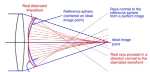
The objective and scanning lens have a great impact on the overall imaging performance. Although it is possible to use off-the-shelf scanning lenses (usually achromatic doublets), these components tend to not be diffraction limited along their full FOV. It’s common that they introduce geometrical aberrations and curved images. Some of this can be corrected by using high quality objective lenses that balance the optical performance of the scanning lens.
Special consideration needs to be taken in choosing the right tube lens. Performance can also be improved if the beam diameter at the scanning lenses is increased (although the diffraction limit will also be reduced). A possible choice using off-the-shelf components could be a 50mm FL achromat (e.g. AC300-50-050-B by Thorlabs), with a 125 mm FL tube lens and a Olympus XLPLN25x Objective lens.
It would be possible to increase the diffraction limited range and reduce the aberrations on the system by improving the design of the scanning and tube lens. With a careful choice of light sources and lens materials, improvements on a simple achromatic doublet with a four elements lens, or addition of additional optical components, it’s possible to make improvements compared to an off-the-shelf counterpart.
Zemax modeling
Zemax modeling is done throughout the design process from concept development to testing the prototype.
Once the initial specifications of the microscope are defined, we can start a first draft using off-the-shelf components and characterize each component individually in terms of aberrations and MTF. Using Zemax, we can model the performance of the off-the-shelf components with black box files, and evaluate how far we are from the set goals. There is a trade-off between the cost of producing a prototype with custom components versus one with off-the-shelf ones. Keeping the performance needs and finances of the client in mind are crucial before attempting to use custom components.
We can then start optimizing one component at a time. The tube lens and the scanning lens are the first choices. We want to simulate and optimize any design in the whole range of light motion and not only in the central part of the lenses. A good design will present similar merit figures when the light beam is closer to the lens edges than its centers. In general, in a microscope design, we will be particularly careful in designing a system with high contrast and high resolution over other design parameters.
It is during this stage that we do a tolerance study that will help us to look at performance limitations and manufacturing needs that will affect prototyping and production costs.
Opto-mechanical design
Once the layout of the elements is determined, the optical engineer will develop a list of positions and tolerances for lens elements relative to each other. For example the tilt, centration, airgap can all have impacts on optical quality.
This optical layout is passed on to the opto-mechanical engineer who will use a program like ProE or Solidworks to design the structure to hold the elements.
Issues like thermal management and stray light prevention are also reviewed between the opto mechanical engineers, the optical engineer and the application specialist.
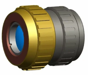
Typical outputs include Solid models of the full system and part manufacturing drawings of each element within the microscope.
