Understanding the purpose of an MTF chart and how to read and MTF chart is an essential skill for anyone involved in the development of products that use optics.
For most applications an MTF test is the single best method to determine lens quality.
In this post we will review the definitions, show example charts, impact of sensor, abberrations, Meridional and sagittal plots and diffraction limited optical systems.
MTF stands for modulation transfer function, this means the transferring of differing optical spatial frequencies through an optical systems.
An ‘Ideal’ optical system is one which transfers optical wave fronts from an object without any deviations. But in any real optical system there is a limit to apeture and and apeture creates diffraction which reduces MTF. As the diffraction spacial frequency grows, the MTF of a system is reduces. An analog in electronics is where devices filter temporary frequencies. MTF of ideal system has formula.
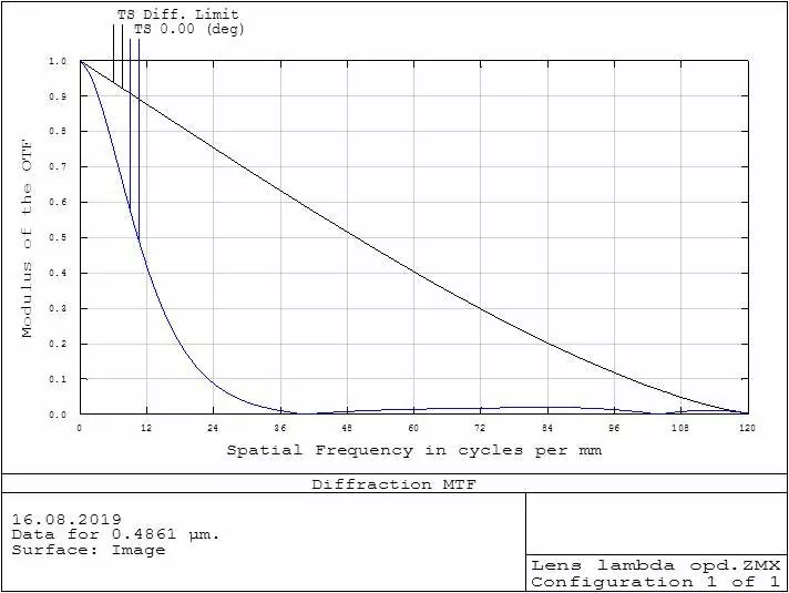
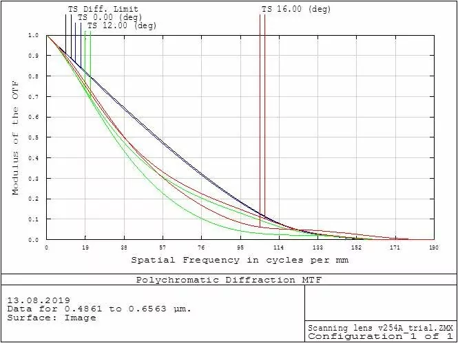
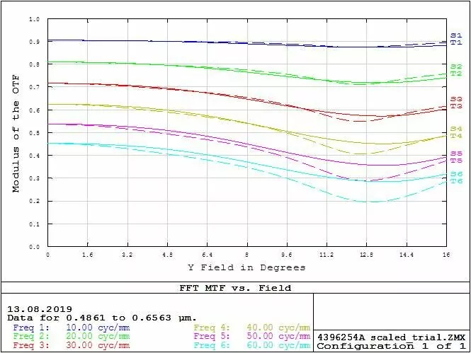
Below are examples of MTF plot from Zemax, on the left image the x axis is spatial in units of line pair per mm and the Y axis is amplitude which also can be called contrast. The different color lines are different fields of view. The black line is plot for ideal system.
On the right image the x axis is field of view and the y axis is contrast/ amplitude.
A human generally needs a contrast of 0.1 or higher to be able to see the difference in lines
In image below, the upper half is a sinusoidal test object and the lower half is an object imaged by a real optical systems. The upper half has perfect contrast the lower half is contract is reduced because of diffraction.

The formula for MTF in an ideal optical system where MTF is defined by the diffraction limit. It is show below as a formula and plotted on an MTF chart in the second image

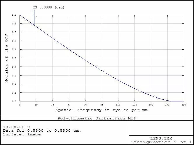
Based on the formula you can determine some fundamental relationships including.
- The larger the cutoff frequency the higher resolution of system
- Aperture is main value in ideal MTF calculation
- The more aperture ( also called NA) the bigger cutoff frequency
- The smaller λ ( wavelength ) the bigger cutoff frequency, the higher resolution of system
Meridional and sagittal plots of MTF
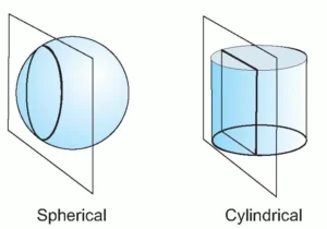
Usually MTF chart includes two plots for selected off axis points of field of view. There is a very small difference because of different apture value from Meridional and sagittal apertures., this come from tilt and other geometrical issues.
In real system the difference can be bigger because of residual aberrations. One of the biggest influences is astigmatism.
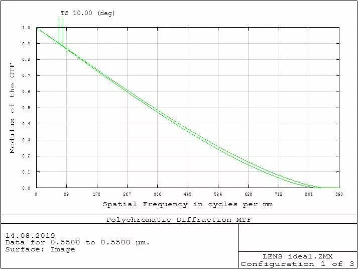
The MTF chart below is from a Zemax model and is close to ideal
But it has slightly lower resolution because of residual aberration which depends on optical performances, number of lens elements and types of glasses.
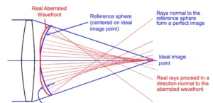
Residual aberration deviates wave fronts going from the object when compared with ideal system. However there is criteria when real optical system can be regarded as ideal. It is similar to tolerance which provides that. This criteria names as Rayleigh λ/4. It means that absolute value of wavefront deviation in optical system has to be not exceed quarter (fourth) of wavelength value. In this example ideal MTF in black, real in blue.
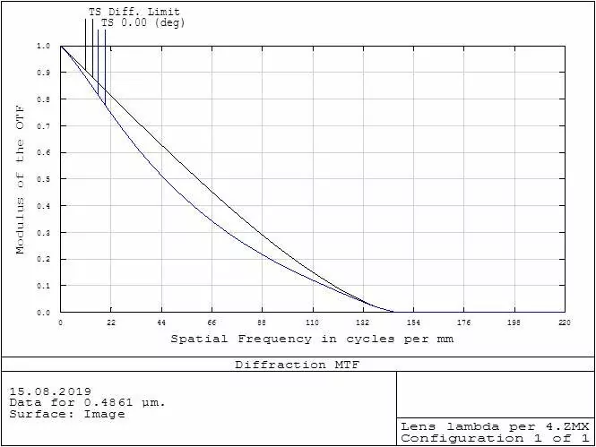
Note, cutoff frequency still as for ideal system. Essential decreasing of MTF is seen for “middle ” spatial frequencies.
Limit of MTF calculation.
When optical system posses big residual aberrations then calculation of MTF is loosing accuracy. Reasonable limit is wavefront deviation in 1 lambda.
With large aberrations MTF cannot be calculated.
